Why use thyristors in high power rectifiers?
Power grid networks deliver electricity as AC (Alternating Current), but some key applications, such as electric vehicle battery charging and Light Rail transport systems, require DC (Direct Current) for economic and efficient operation. For example, standard Rail DC voltage systems operate across Europe, nominally at 600V, 750V, 1500V and 3000V, but the power network provides much higher voltage AC. Trackside equipment is used to covert the power network AC to DC using transformers & rectifiers. More generally, some applications will need simply to provide a constant source of DC, while others may need control to adjust the output to fluctuations in demand. This need for control is the major reason for using thyristors in rectifier circuits.
What is a controlled rectifier?
Alternating current, as its name suggests, means current flows in both directions during a single cycle. In its most basic form, a single phase rectifier circuit consists of one, two or four diodes, arranged in order that the current is forced to flow in one direction.

Fig 1. One, two and four diode rectifier circuits – single phase, and associated wave forms.
A thyristor is a semiconductor device which can be used to switch current on and off. When used in rectifier circuits, thyristors allow current to be controlled more accurately than diodes, which can only be ON or OFF. A thyristor can be triggered to allow current to pass in a graduated manner, by firing (switching on the thyristor) at a precise time, therefore controlling the conduction angle. The level of control required for a given application will determine how thyristors are used in the circuit. Half-controlled rectifiers use thyristors in place of diodes on either the positive or negative side of the circuit, whereas a fully controlled rectifier uses thyristors entirely.

Fig 2. Positive half control and fully-controlled rectifier circuits – single phase.
Multi-phase rectifier circuits
Multi-phase AC inputs are rectified using diodes on each phase. As with single phase supplies, these rectifiers can be uncontrolled (diodes only), half-controlled or fully controlled using thyristors.

Fig 3. Fully-controlled rectifier circuit – three phase & six phase.
Thyristor Controlled rectifiers in systems
The basic rectifier components convert AC to DC, but the output has to be supplied to the system in a suitably protected way. This includes blocking any unwanted noise or voltage spikes which may be generated from the AC line or during the rectification of the supply. The semiconductors used in these applications are typically very robust but it is normal to protect them using quick blow fuses, specifically designed for that purpose. In the event of a fault leading to overheating, thermostatic trips are incorporated into the assemblies, and to reduce voltage spikes, snubber circuits are connected across the thyristors.

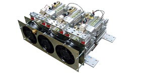
Fig 4. Typical configuration for a thyristor controlled rectifier assembly.
Putting it all together – building a thyristor controlled rectifier
Designing the rectifier with the correct configuration, selecting the optimum semiconductors, fuses, trips and spike protection devices, goes hand-in-hand with thermal management of the system as a whole. What are the losses of the thyristors at operational temperature? How much heat is going to be dissipated, and how big will the heat sink therefore need to be? Is forced air convection required via fans on the assembly? Where is the equipment located? What industry standards and compliances need to be considered?
Power Products International have over 30 years of experience in the design and manufacture of this type of product, so if you have an application requiring reliable, robust rectifier equipment, contact us to discuss how to make it happen.